In the last several years a number of graphics engines have been released that are rendering vast amounts of terrain.
Some of the more recent ones are now rendering over 32km (20 miles) of viewable terrain.
The ability to render this much viewable terrain has come mainly from the increased power in consumer level video cards.
Otherwise (with the exception of deferred shading) the terrain rendering techniques have remained pretty much the same as they were in years previous.
Level of Detail
To render several kilometers of terrain you need to employ one of the various level of detail (LOD) techniques.
LOD is a group of techniques that share the common goal of reducing the polygon count and complex shader use on distant terrain.
If you attempt to render a large amount of terrain without reducing any of the detail you will quickly find out that the average video card will not be able to render it at a reasonable speed.
However even a simple LOD implementation will allow you to draw huge amounts of terrain and at the same time maintain an impressive frame rate.
There are many different LOD algorithms that dynamically reduce distant terrain detail.
However most of them cause terrible terrain "popping" effects that are very distracting to the eye as you approach distant terrain.
As well these same dynamic algorithms generally have issues with terrain edges that don't align correctly causing noticeable cracks in the terrain.
To avoid these two common problems with dynamic LOD algorithms we will instead cover a method that uses pre-built terrain which is free of these issues.
The method we are going to use is called node based LOD.
Node Based LOD
Node based LOD is a method where the entire terrain is evenly broken up into multiple nodes.
Each node is the same size and covers a specific distance such as 128 meters by 128 meters.
Now what is most significant about this method is that each node has multiple quality levels.
For example a node might have a low, medium, and high quality version which has been pre-built in a terrain editor.
Then when we render that node we determine the distance it is from the camera and from that we pick which quality version to render.
If it is close to the camera then we render the high quality version, if it is a bit further we render the medium quality,
and if it is past a certain range but within the maximum render distance then we draw the low quality version.
You can of course have as many quality levels as you like, but generally three or four qualities is sufficient.
The next part of node based LOD is that we use background threads to load and unload nodes as the camera moves around the terrain.
Most video cards don't have enough memory to hold several kilometers of multiple quality terrain nodes so loading/unloading is necessary.
And to keep our frame rate from being disrupted we need to use background threads to do the loading.
For example as the camera moves closer to medium quality node it will need to load in the higher quality version on a thread.
Once that is loaded it then makes the switch to rendering the high quality version.
And finally it unloads the medium quality version it was using previously.
Note that in DirectX 11 you should not be creating and releasing vertex and index buffers to perform the loading and unloading of terrain nodes.
Doing this will cause the video card to lock and will also cause memory thrashing.
You should instead be using an array of pre-initialized dynamic vertex buffers for each quality level.
These buffers are reused instead of being released and recreated.
Since the buffers for each quality level are the same size you can just use the Map function to overwrite the old data.
For example if you have nine high quality nodes then you should have an array of ten vertex and index buffers dedicated just to high quality nodes.
As you need to load a new high quality node you use the tenth unused vertex/index buffer and Map the terrain node data into it
and give the node a pointer to it.
Then you mark the previous high quality vertex and index buffer that is no longer being rendered as unused with just a boolean flag.
For each quality level we also have a shader (or multiple shaders).
The super complex shader you use for up close terrain should never be used for distant terrain.
Also try to sort by shader when rendering and try to minimize constant buffer updates to get the best frame rate you can.
The final part of node based LOD is that we render the nodes according to the location of the camera.
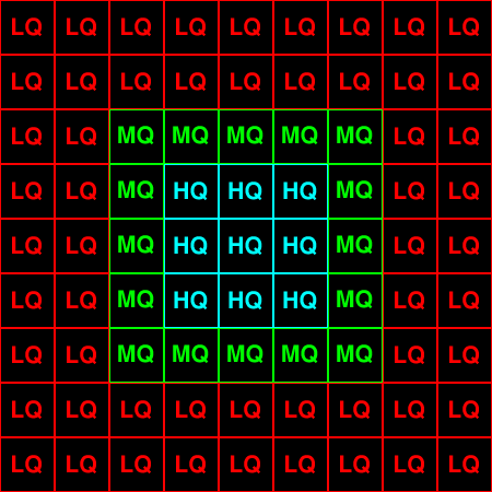
The node that the camera is currently in and the eight nodes around it must be rendered as high quality.
This allows us to always keep an area that surrounds the camera in high quality and it also gives us enough time to load more high quality nodes as the camera moves.
Note that high frequency effects such as normal mapped textures will not show up in the distance so there is no need to do more than nine nodes of high quality terrain.
The next 16 nodes that surround the 9 high quality nodes are rendered as medium quality.
You could do even more than 16 (such as the next 24 nodes that surround those 16 nodes) in medium quality,
but this is something that is completely flexible and is up to you to decide once you have tested things out.
Finally all the remainder of nodes that are rendered beyond that are done so in low quality.
There can be exceptions of certain special nodes that we may want more distant detail on, but we'll discuss that later.
Here is a diagram showing what I just explained:

Now even though the diagram only shows two levels of low quality nodes you should do many more.
But first you need to determine a terrain budget to figure out exactly how many you should be drawing.
We'll discuss the budget shortly but we need to first talk about node culling.
Node Culling
Using node based LOD allows us to very easily cull nodes that aren't viewable.
Each node is a specific size at a specific location so we can do a quick frustum test again a cube shape to quickly cull nodes from being rendered.
You can even create a quad tree to do the culling at a higher speed.
On average at any given camera location you will never be viewing more than 30 percent of the terrain.
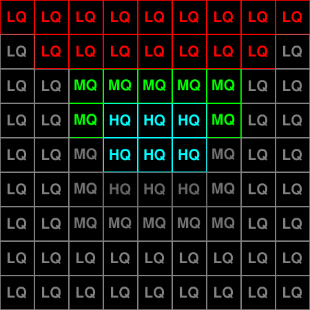
For example the diagram below shows the nodes that are culled in grey if you are in the center looking upwards:

The reason I am discussing node culling now is because it relates heavily to the terrain budget.
All of the culled surrounding nodes must still be loaded into memory, but our frame rate only reflects what we are drawing at that moment.
So keep this in mind when creating your terrain budget.
Terrain Budget
Before embarking on rendering massive amounts of terrain we should probably do some planning in advance.
The whole idea of measure twice and cut once can save us a lot of coding and help us go down the right direction from the start.
We want to determine as close as possible the amount of terrain we should be rendering based on our target system specifications.
We also need to take into consideration what else is going to be rendered and what percentage our terrain is allowed to take up.
Below is a quick example to help us make decisions about how much terrain to render.
Rough Poly Budget = About 500,000 polygons.
Memory Budget = Assuming target spec is 1GB video card, use about 500MB for terrain, remainder for trees, buildings, etc.
Leave enough room in memory (about 10 percent) to provide a cushion in case other issues show up.
With this rough spec in mind we can now setup the node qualities:
High Quality Node
Full Graphics: Normal Mapped with dynamic lighting and four layers of texture blending.
128x128 * 2 triangles = 32,768 polys
Memory: 32768 polys * 3 vertices * 64 bytes (12 byte position * 8 byte tex * 12 byte normal * 12 byte tangent * 12 byte binormal * 8 byte tex) = 6144 KB (6 MB)
9 Nodes = 54 MB memory, 0 to 384 meter terrain coverage, 294,912 polys
Textures: 4 terrain textures 512x512, 1-2 normal maps 512x512, 1 blending texture 512x512
Medium Quality Node
Reduced Graphics: Color mapped with dynamic lighting only.
64x64 * 2 triangles = 8,192 polys
Memory: 8192 polys * 3 vertices * 36 bytes (12 byte position * 12 byte color * 12 byte normal) = 864 KB (0.84 MB)
16 nodes = 13.5 MB memory, 384 to 640 meter terrain coverage, 131,072 polys
Textures: None
Low Quality Node
Reduced Graphics: Color mapped with dynamic lighting only.
16x16 * 2 triangles = 512 polys
Memory: 512 polys * 3 vertices * 36 bytes (12 byte position * 12 byte color * 12 byte normal) = 54 KB (0.05 MB)
24 nodes = 1.25 MB memory, 640 to 896 meter terrain coverage, 12,228 polys
Textures: None
Low Quality Node (second layer)
Reduced Graphics: Color mapped with dynamic lighting only.
16x16 * 2 triangles = 512 polys
Memory: 512 polys * 3 vertices * 36 bytes (12 byte position * 12 byte color * 12 byte normal) = 54 KB (0.05 MB)
32 nodes = 1.69 MB memory - 896 to 1152 meter terrain coverage, 16,384 polys
Textures: None
So this spec gives us the same terrain as we diagrammed earlier.
But of course we want to add more low quality nodes to cover even more distance.
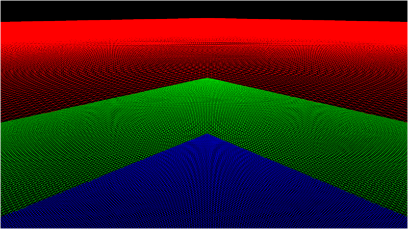
To test an average polygon count I wrote a quick program to render just plain colored nodes but still use the vertex count for low, medium, and high quality nodes that we defined above.

As you can see it rendered the nodes the camera was over with higher polygon counts (blue), the more distant medium nodes with half the polygon count (green), and then the distant nodes (red) in low polygon mode.
The results that when I rendered 16x16 node terrain (2km) I got on average about 250k polygons.
When I increased the node count to 25x25 (3km) I got on average about 375k polygons.
Also I was well over 1000fps on my good computer and just over 100fps on my weak laptop, so this gave me an indication of how far I could take things with the current spec and node quality setup I defined here.
Now also note that frame rates are just rough, but they give us a general idea.
In fact most video card drivers don't push the card to maximum unless absolutely required so that they can conserve on energy.
So you could in fact render even more nodes and notice your frame rate is even better.
Though once again this is just a rough test to see what I should aim for to start with.
And like always if we code things well enough it should be simple to change a couple variables and render more nodes or add new quality levels.
All of these things will need to be tested before we decide on the end state of our quality levels and node counts.
Terrain Building
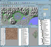
To build good terrain you generally need to write your own terrain editor.
Especially since we are planning to export multiple quality levels for each terrain node it makes more sense to write a tool that will automatically do it for us.
For implementation the vast majority of terrain editors use Perlin noise to generate fractal terrain,
and then they add numerous tools and other algorithms to the editor so that the terrain can be modified to achieve a specific look.
Some terrain editors go even further and use biological algorithms to place plants, trees, river erosion, and so forth.
When building a terrain editor it is usually a good idea to use something quick like Visual C++ to quickly prototype a program.
Remember that artists prefer things like sliders and dials instead of text and numeric input boxes, and Visual C++ has those built in already.

Terrain editors can be a huge project on their own, but for the time being it is sufficient to build something that can generate perlin noise and export it to your own model format.
Build the export function to export three quality levels for each 128x128 meter section of the terrain.
High quality would be a 129x129 portion of the height map. Medium quality would be the same 129x129 section shrunk down (preferably an edge preserving re-sample) to 65x65.
And finally the low quality version would be a 17x17 height map that was sampled down from the 129x129 section.
One thing to keep in mind is that it is common to use just 8 bits to represent the height giving only a range of 0 to 255.
This precision is extremely lacking isn't useful for creating large realistic terrain.
It is generally better to go with a 16 bit height value instead even if you don't use the entire 16 bit range.
Implementation
Now that you have a simple terrain editor that can export to your specific terrain model format you can now start rendering the terrain nodes as I detailed above.
There is no need for any new graphics code in this tutorial as the previous terrain tutorials have already shown you all the code you will need to complete this project by yourself.
However there are some extra details that I would like to discuss.
The first thing is that some nodes always require at least a minimum medium quality even in far distance, for example mountains.
So in the terrain rendering engine you should have a method of ensuring that some nodes can be flagged to never lower their quality below a certain limit.
The second thing is that maybe you found a limit of only being able to render 16km but have a 32km terrain.
This is not an issue because it just involves loading more low quality nodes as they come into the 16km viewable distance and then unloading the low quality nodes that are outside of that distance.
Remember once again to reuse vertex and index buffers even for low quality nodes.
In addition a trick that is used to bring distance nodes in smoothly (instead of popping into view as they get loaded at a distance) is to set the far view plane correctly.
For example if our limitation is 16km viewable distance then set the far view plane at 15.8km.
Then make sure that you do load nodes that come into the 16km range before they get to the 15.8km distance.
Now when the node comes into range of being rendered they will be drawn smoothly polygon by polygon using the far plane culling.
Once again we are always looking at ways to remove the popping that occured with traditional LOD methods.
Also since I used color maps as an important tool for medium and low quality nodes I would like to explain how I build them.
I generally render a high quality node by itself from a top down perspective.
I flatten the terrain and set the light to be straight down.
At this point I take a screenshot and then shrink it down to the medium and low quality node sizes as a color map.
The final thing I want to add is don't be afraid to go really low detail with the shaders on nodes that are outside of the high quality distance.
If you put a high quality node beside a medium quality node at a medium distance you will notice they barely look any different other than the lighting looks softer on the medium quality node.
And considering you will be covering a lot of the terrain with buildings, trees, and so forth the lighting becomes even less noticeable.
Summary
So you now understand the basis behind node based LOD and how to implement it to draw several kilometers of terrain.
The key to getting a massive range is to test and try pushing the limits with low quality nodes and optimizations around them.
Also there wasn't any code for this tutorial since all the previous tutorials have already covered all the graphics techniques you need to render terrain using DirectX 11.
To Do Exercises
1. Create a terrain budget.
2. Create the terrain editor to build and automatically export Perlin noise generated terrain into the terrain model format with three quality levels.
3. Write the terrain rendering program as detailed above. Attempt first for about 4km of viewable terrain.
4. Update the program to render at least 8km of viewable terrain and another 8km that is not viewable so that 16km of terrain can be navigated.
![]()
![]()